Mm 3000 Joystick Wiring Diagram
The HS Series miniature joystick is a single pole MOM-OFF-MOM micro switching joystick. Ground wire to the ground loop and the appropriate JAMMA wire to the normally open terminal as illustrated.
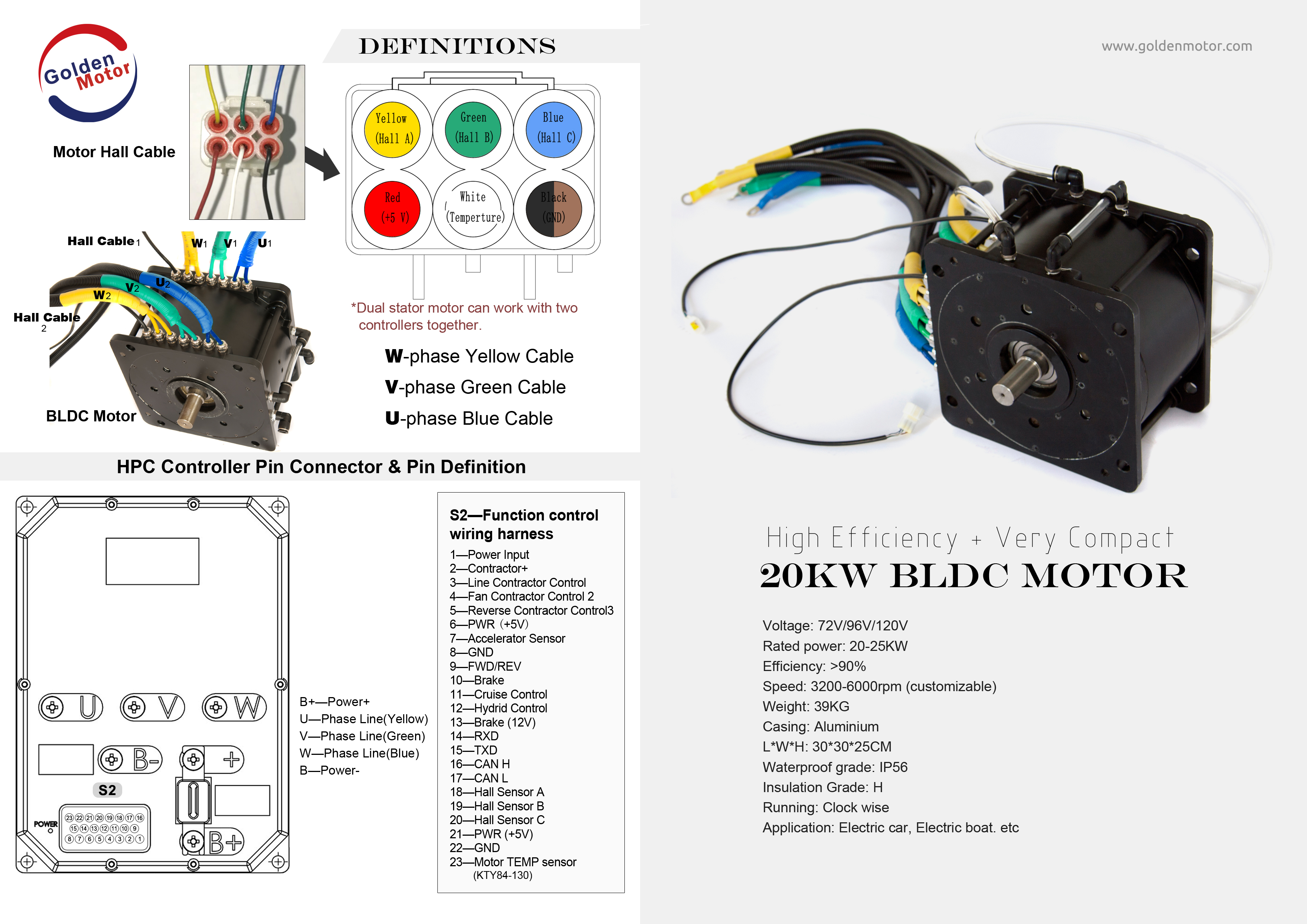 Brushless Motors Bldc Motor Sensorless Motor Motor Controllers Foc Controller Field Oriented Control Brushless Motor Controller Bldc Controller Axial Flux Brushless Motor Axial Flux Pm Motor
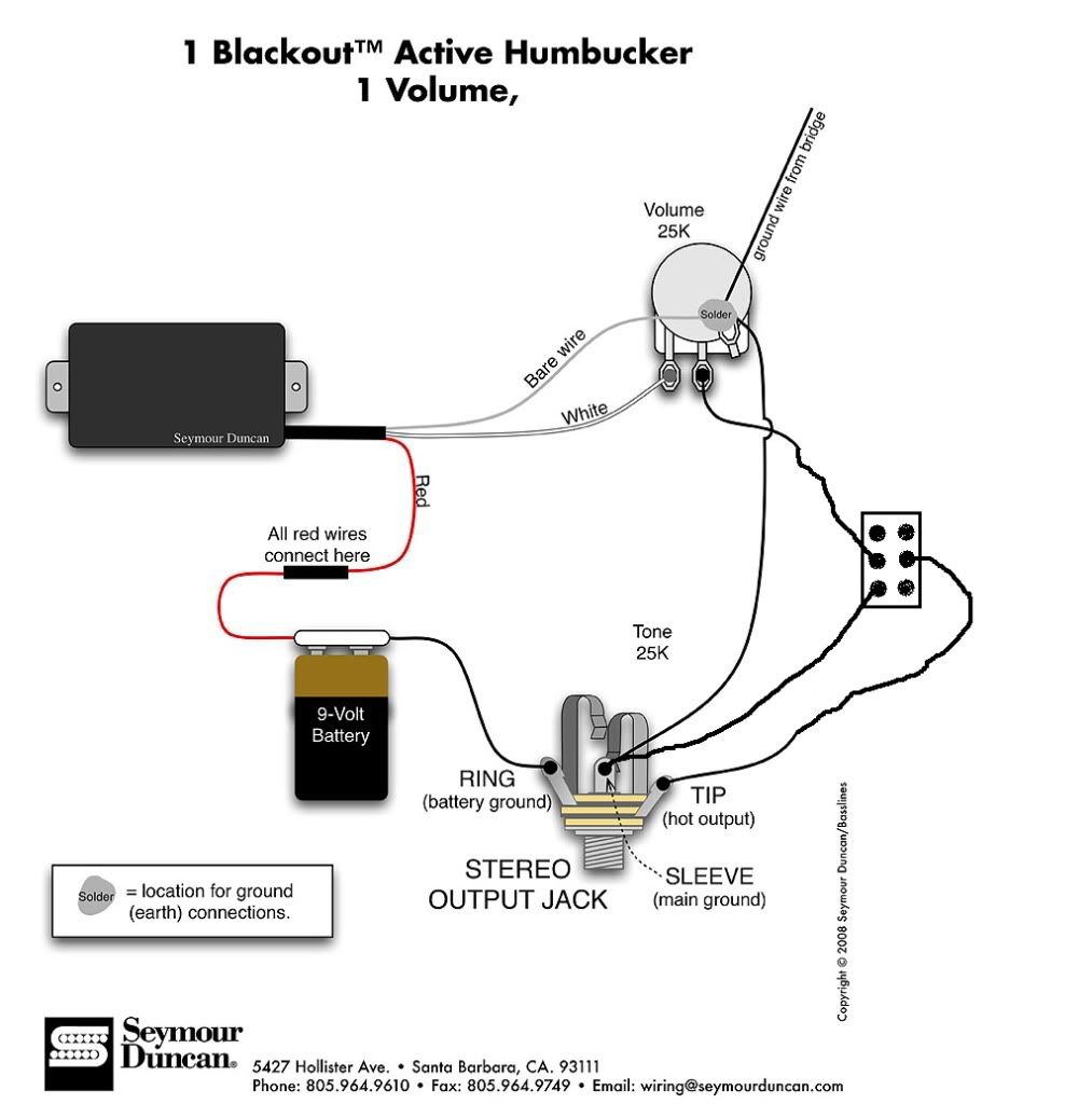
Can you tell me which color wires are.
Mm 3000 joystick wiring diagram. 08102018 08102018 5 Comments on Sno Pro 3000 Wiring Diagram Does the older Curtis joystick controller have an orange ground wire connected to it. Which wires in the 5-pin joystick harnesses are for which direction ground on Seimitsu LS and Sanwa JLF joysticks Millard Aw January 05 2019 2310 Follow Originally from ticket 140. With a class leading installed depth of.
Analog joystick wiring diagram. Mame Joystick Usb Wiring Diagram There are many sorts of electronic gadgets on the market. In the table below X indicates that.
Wire joystick to arcade bonnet. According to Usb Joystick Wiring Diagram you will find only four wires used in the cableTypically it uses black green white and red cable colours. In addition it can.
Connect the components based on the figure shown in the wiring diagram using a M-M pin connector. Western Snowplow Wiring Diagram western snow plow installation manual western snow plow joystick wiring diagram western snow plow solenoid wiring diagram Every electric structure is composed of various distinct pieces. A wiring diagram is a simplified standard pictorial representation of an electric circuit.
Fisher plow controller wiring harness ford ka fuse box numbers for diagram schematics western handheld full version hd quality diagraminfo virtual edge it 6 pin rheem low voltage seniorsclub device spend hazzart help 3 plug problems the largest community snow plowing and ice management professionals find discussions on weather equipment tips growing your business enimsc series shock boss. Se elektrisk diagram side 1 Color codeconnector see Electrical diagram page 1 FarbkodeConnector Siehe Elektrodiagram Seite 1 Symbole des coleursconnecteurs voir diagramme elec-trique page 1 Adapterring. It shows the elements of the circuit as simplified forms and the power and signal.
In this Instructable well be going over three different switches and learning how to control an actuators extension and retraction. The three rocker switches we will be going over are our RC-03 rectangular switch our RC-07 round switch with a ligh. Vcc from joystick to 3v on adafruit feather.
The 3000 Series is the very latest generation in high precision contactless joysticks. Long trouble-free life is assured with the latest Hall effect. This plow is a single plug setup Posts.
The ground is usually shared. Rocker Switch and Joystick Wiring W Linear Actuators. The cable can be used to transfer information from one device to another.
When wiring a PCB extracted from a pad controller you need to solder a wire to the signal for each of the needed buttons and one or more wire to each of the unique grounds used by those signals. Numerous button styles are available and the HS series may be specified for 2-way 4-way and 5-way operationMain features5-way with. Joystick module 1 Pin M-M connectors Breadboard USB cable 1.
Every joystick and button micro switch must be connected in the same manner. So you want to convert your good old suncom f15 talon joystick from this. Collection of sauer danfoss joystick wiring diagram.
Minute Mount 2 Wiring Harness Today Wiring Schematic Diagram Fisher Joystick Harness Schematic Chart Plowsite 8ar3200g Alternator Product Details Prestolite Leece Neville Diy Fisher Minute Mount Snow Plow Boss V. The red one is to get. 5V pin is connected to the 5V power supply.
03 tahoe fuse box diagram 03 trailblazer wiring diagram 04 acura rsx fuse box diagram 04 saab 9-3 fuse box diagram 05 toyota tundra stereo wiring diagram 06 saturn ion fuse box diagram 07 chrysler sebring fuse diagram. For instance in case a module is usually powered up and it sends out a new signal of half the voltage in addition to the technician will not know this hed think he provides an issue as he or she would expect a new 12V signal. Wiring diagram for my cnc machine wire center de soto car pdf manual fault codes dtc mvh pioneer stereo x560bt circuit resource 91 geo metro full version hd quality speakerdiagram cooking4all it amana draw choice fiocouture e scooter mustang fuse box stangnet schematics simple triumph ls3 engine parts podewiring yenpancane jeanjaures37 fr curtis snow pro 3000 1998 camaro Read More.
Black wire serves as ground just like in any other apparatus. In the actual circuit most of the wiring is made. Most of them use USB cable.
Https Www Montalvo Com Uploads 98 Idc Us Manual Pdf
 Curtis Snow Plow Light Wiring Diagram Directv Genie Install Diagram Swm 3 Wireless Dodyjm Nescafe Jeanjaures37 Fr
 Curtis Plow Wiring To 98 Gmc Truck 2003 Tacoma Wiring Diagram Piooner Radios Yenpancane Jeanjaures37 Fr