6 Volt Positive Ground Wiring Diagram 3 Terminal Regulator
Wiring diagram for 1951 COE Truck. Cable off the battery go to ground and the neg.
 29 Ford Alternator Wiring Diagram Bookingritzcarlton Info Alternator Voltage Regulator Electrical Wiring Diagram
57310DY For models with 6 Volt CUT OUT relay NOT voltage regulator Cut out relays have 2 terminals on 1 side and 1 terminal on the other side Voltage regulators have 3 terminals on 1 side and 1 terminal on the other side or under the regulator base.

6 volt positive ground wiring diagram 3 terminal regulator. Wiring diagram for 1951 Truck. If you want to create your wiring from scratch please use the correct type wire and terminals. So does that mean the pos.
It is connected by a positive wire to the generator. The generator is the first electric motor connected to the positive cable of the battery. 6 VOLT ELECTRICAL TIPS TRICKS Ill use the term VOM to denote voltohmampmeter.
The starter cranks a stock flathead engine at 100 rpms. May apply to others. May 03 Simple visual explanation of the wiring of the 6 volt Generator Regulator on My Farmall Super A 6 Volt Positive Ground.
The voltage regulator field. Wiring diagram for 1948-50 COE Truck. Wiring Diagram consists of several in depth illustrations that show the link of various products.
Take a look at the diagram below. 7 Connect a good ground to terminal G on the back of the gauge the ground is only used for the gauge. It is usually square with five or six terminal screws on its face.
With few exceptions the early systems were 6-volt and used a DC generator for recharging the battery. 16022019 16022019 3 Comments on Wiring Diagram For 6v Tractor Voltage Regulator Positive Ground Solenoid Start This walk-thru is based on the original 8N tractor 6 volt wiring. May apply to others.
This walk-thru is based on the original 8N tractor 6 volt wiring. Go to the starter. The starter current draw on a Ford V-8 through 1948 is 550 amps does not include V-8 60s.
I got an alternator the label says delco 10si 1 wire hookup 6 volt positive ground for my super a. All our work is guaranteed. Connect the wire to the terminal marked B sometimes this terminal is marked BATT.
Simple visual explanation of the wiring of the 6 volt Generator Regulator on My 1953 Farmall Super A 6 Volt Positive Ground. Yes your 1946 John Deere A has a positive ground. We could go smaller for a 12 volt system but if someone decides to switch back to a 6 volt system the wiring would all have to be changed.
Switch manufacturers consider OFF as. Yes note the ground cable Key 12 is connected to the positive terminal on the battery and the negative cable Key 1 goes to the starting motor. 6 volt alternator wiring diagram.
May apply to others. The 1949 1951 engines crank 130 rpm without an automatic. Wiring diagram for 1948-50 Truck.
If you are using a coil with external ballast resistor connect this wire to the battery side or key switch side of How To Wire Alternator 12-VOLT NEGATIVE GROUND 3 WIRE. Connect the positive battery cable wire -- usually red -- to the regulator. System power rail to its output e.
Wiring diagram for 1952-54 Ford 6 Wiring diagram for 1952-54 Ford 8 Wiring diagram for 1949-51 Ford OD. This is because these components are insulated well enough to withstand a lot more than 12 volts. It contains instructions and diagrams for different varieties of wiring methods.
Its components are shown by the pictorial to be easily identifiable. Jun 20 wiring diagram discussion in the Farmall International Harvester IHC forum at Yesterdays Tractors. 6 Connect a minimum 10AWG wire from the 12V terminal of the starter solenoid to terminal I on the back of the gauge.
Step 6 Figure 1 Snap in the DA plug and connect the red wire to the output side of the alternator 1032 stud take the long wire and connect to the side of the coil. Locate the volt regulator on your vehicle or machine. 6 Volt Positive Ground Wiring Diagram 3 Terminal Regulator It is far more helpful as a reference guide if anyone wants to know about the homes electrical system.
Connect the generator or alternator wire to the regulator. 6 VOLT TO 12 VOLT SYSTEMS. 5 Connect a minimum 10AWG wire from the Alternator OUTPUT to terminal S of the amp gauge.
Is the least efficient diagram among the electrical wiring diagram. In 1957 all American car manufacturers standardized their electrical systems at 12 volt negative ground to accommodate aftermarket manufacturers and to take advantage of the new solid-state electronics which did not work well in positive. Getting schematic diagram alternator 4 wire hitachi 85 a is easy and simple.
We now offer complete rebuilding services for Starters generators Alter. Some earlier 9N and 2N tractors had one-wire generators and used a cutout instead of a voltage regulator. The corresponding terminal for the generatoralternator wire is marked an A or G sometimes ARM or GEN.
I use the same sizes for 12 volt wiring for all the same reasons. May 03 Simple visual explanation of the wiring of the 6 volt Generator Regulator on My Farmall Super A 6 Volt Positive Ground. Many of those were later converted to the 8N type generator and voltage regulator so this Two small screw terminals on the side of the generator are for Ground.
6 Volt Positive Ground Wiring Diagram Wiring Diagram 6 Volt Positive Ground Wiring Diagram Fuel Tank Wiring Diagram â 6 Volt Positive Ground Wiring Diagram. Positive ground rectifier diode trio brush holder with 2 new brushes 2 springs retaining pin drive end 6203-2RS bearing slip-ring end needle bearing 6-volt self-exciting voltage regulator stud kit regulator port block off plug 4 new screws 3 insulated 1 plain.
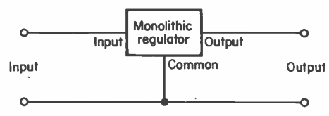 3 Terminal Fixed Voltage Regulators Working And Application Circuits Homemade Circuit Projects
 Great Wiring Diagram For Horn Relay Horn Relay Simple Wiring Car Horn Electrical Diagram Horns
 1973 Vw Bus Alternator Wiring Vw Vocho Motor Vocho Motor De Vocho
 230v Ac To 5v Dc Converter Lossless Electrical Engineering Stack Exchange Power Supply Circuit Electrical Engineering Books Power Supply


